

1. Overall structure and logistics design of the production line
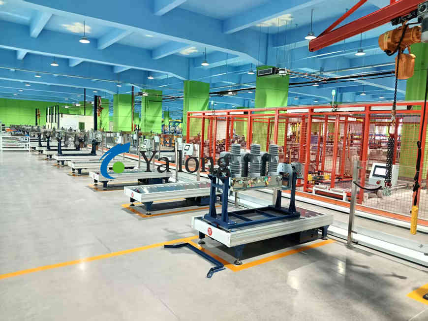
The assembly line adopts a modular segmented layout, and the main body consists of a non-powered roller conveying main line and a steel universal ball adapter station to form a “non”-shaped structure. Products are carried by accompanying tooling boards, realizing flexible flow between the main line and the workstation.
The entire line uses an aluminum profile frame as the skeleton and cooperates with the Fulai wheel conveying system, which not only ensures the stable transmission of heavy circuit breakers (a single unit can weigh up to 350-450kg), but also realizes the physical isolation of the assembly station and the logistics channel.
The production line control system takes Siemens PLC as the core and is equipped with a color touch screen man-machine interface to support equipment configuration, status monitoring and abnormal maintenance guidance functions. In terms of energy-saving design, each power drive section automatically stops when there is no transportation task, and immediately wakes up when a workpiece enters. The no-load power consumption of the entire line is controlled within 70KVA.
2. Core assembly process
The assembly of pole-mounted vacuum circuit breakers follows the process logic of “from inside to outside, from static to dynamic”. The process chain of typical ZW32 series products is as follows:
Phase 1: Ontology skeleton construction
- Online switch outer frame: The tooling board carries the bottom frame of the circuit breaker into the first position to complete horizontal positioning and clamping.
- Vacuum sealed pole installation: Insert the vacuum sealed pole assembly (including ceramic shell, copper-chromium contacts, and longitudinal magnetic field interrupter) vertically into the three-phase insulating sleeve. This link requires extremely high coaxiality, and requires the help of precision guide fixture ensures that the verticality error between the pole and the bottom frame is ≤0.2mm/m.
- Current transformer embedding and primary wiring: External protective CT is configured in phases A and C to complete the flexible connection between the primary conductor and the pole moving contact. The connection adopts a silver-plated copper braided tape soft connection structure to avoid mechanical stress transmission during operation.
Phase 2: Integration of operating mechanisms
- Assembly of opening and closing spring and transmission link: Put the energy storage spring, cam drive mechanism and spindle assembly into the mechanism box, and tighten them in sequence with a special torque wrench to ensure that the pre-tightening force of the opening spring conforms to the design curve.
- Secondary circuit wiring: Lead the control wires, signal wires and power wires from the mechanism box and connect them to the aviation plug base. The wiring harness must avoid the trajectory of moving parts, and reserve electromagnetic compatible shielded ground terminals.
Phase 3: Performance verification and withstand voltage assessment
- Mechanical running-in test: Conduct 200 no-load opening and closing cycles on a dedicated running-in bench to test the mechanical life of the operating mechanism (required ≥10,000 times), and synchronously monitor the coil current waveform and travel-time characteristic curve.
- Mechanical characteristics test: Use a special tester to record the opening and closing speed, synchronization, overtravel and opening distance parameters. The opening distance of ZW32-12 vacuum interrupter is usually controlled within the range of 8 – 12mm.
- Power frequency withstand voltage and loop resistance measurement: Apply power frequency 42kV/1min withstand voltage test between the fractures, and the loop resistance value must be ≤60μΩ (630A rated current specification).
Phase 4: Attachment integration and final inspection offline
- Isolating switch assembly: Install a three-position isolating switch on the side of the circuit breaker body to complete the pressure debugging of the main contact.
- Floor and protective cover installation: Stainless steel or Dacromet coated box is used to improve outdoor corrosion resistance.
- Comprehensive inspection of finished products: Conduct the last appearance inspection, confirm the fastener anti-loosening mark and check the nameplate parameters. The qualified products are transported to the offline packaging area by the roller line.
3. Key process control points
- Sealing integrity of the vacuum interrupter: The pole fixing and sealing process adopts epoxy resin or silicone rubber integral pouring process to completely encapsulate the vacuum interrupter in the insulating sleeve to eliminate inter-pole short circuit caused by condensation and achieve “20 years of maintenance-free” design goal. During the assembly process, the environmental temperature and humidity (0 – 45°C, relative humidity ≤80%) need to be strictly controlled to avoid bubbles or micro-cracks on the packaging interface.
- Synchronization adjustment of the operating mechanism: For permanent magnet operating mechanisms, the action threshold of the opening and closing coils needs to be accurately adjusted through a PLC-controlled running-in system to ensure that the three-phase opening and closing synchronization is ≤2 ms. The spring mechanism needs to check the meshing clearance of the energy storage motor drive chain to prevent idle closing or refusal to disconnect faults.
- Quality traceability system: The entire line introduces the MES manufacturing execution system to bind the part batches, assembly parameters, test data and operator information of each circuit breaker throughout the life cycle, realizing a “one object, one code” digital quality file.
4. Technical parameters and adaptation capabilities of the production line
The assembly line has strong product flexibility and is compatible with multiple voltage levels of 12kV/24kV/40.5kV, as well as two mechanism types: spring operated and permanent magnet operated.
Taking 12kV products as an example, the design rhythm is 24 minutes per unit, the daily production capacity is 20 units (8-hour single shift system), and the annual production capacity can reach 5000 units.
The noise of the entire line is controlled below 75dB, and the air source pressure is 6.5kgf/cm². Each workstation is equipped with double-sided air source quick connectors and power sockets with leakage protection to support subsequent workstation expansion and transformation.
If you have any questions or needs about the automated assembly line, please contact us via email: yu.yalong@outlook.com